Front Speakers
This is the first loudspeakers I have designed and made.
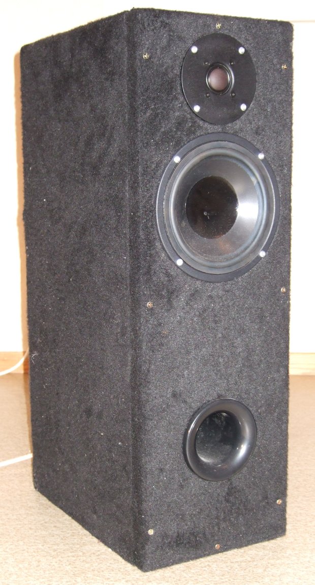
The loudspeaker elements⌗
Since this is a two way system I had to find a tweeter and a bass-midrange speaker to cover the whole frequency range of the speaker. I decided to use the tweeter Seas H1189 27TDFC and the bass-midrange Peerless CSX 176 H.
Box Calculations⌗
I have calculated the box after the formulas given in Høyttalerbok. I will here show the calculations. To ses if a closed box or a vented box is best suited the EBP must be calculated
\[ \begin{equation} EBP = \frac{F_s}{Q_{es}} = \frac{38.0}{0.53} = 71.7 \end{equation} \]
Since EBP is over 55 it is best suited in a vented box. Formula (2) gives the ideal volume for maximum linear response. Formula (3) gives the port tuning frequency. The roll of frequency is given by formula (4).
\[ \begin{equation} V_B = 20V_{AS}Q_{ts}^{3.3} = 20 \cdot 27.7 \cdot 0.43^{3.3} = 34.2l \end{equation} \]
\[ \begin{equation} F_{port,-3dB} = f_s \left(\frac{V_{AS}}{V_B}\right)^{0.31} = 38 \left(\frac{27.7}{34.2}\right)^{0.31} = 35.6Hz \end{equation} \]
\[ \begin{equation} F_B = f_s \left(\frac{V_{AS}}{V_B}\right)^{0.44} = 38 \left(\frac{27.7}{34.2}\right)^{0.44} = 34.6Hz \end{equation} \]
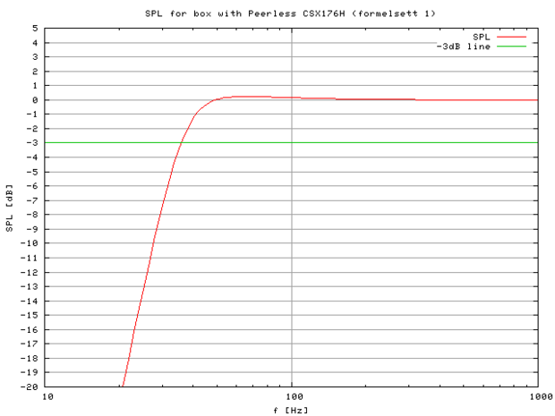
I have made a gnuplot script which calculates and plots the frequency response of the loudspeaker. The script calculates the ideal volume and tuning frequency, but it is possible to manual override these values to see the effect of the changes. I decided to make the box 30l to get a little more power at low frequencies. That makes \(F_B = 36.7Hz\) and \(F_{Port,-3dB} = 37.1Hz\). The calculated low frequency response is shown in the picure below.
To get the desired tuning frequency a suitable port needs to be calculated. First one needs to calculated a minimum diameter, then choose an availabel diameter and calculate the length. The minimum diameter which gives no blowing noise at maximum power is calculated in equation 5 to 7.
\[ \begin{equation} X_{MAX} = \frac{d - hg}{2} = \frac{33 - 6}{2} = 13.5mm \end{equation} \]
\[ \begin{equation} V_D = \frac{S_D X_{MAX}}{1000} = \frac{143 \cdot 13.5}{1000} = 1.93 \end{equation} \]
\[ \begin{equation} D_{MIN} = \sqrt{\frac{a(PV_B)^{0.3} \left(\frac{V_D^2}{F_B}\right)^{0.25}}{N}} = \sqrt{\frac{8(150 \cdot 30)^{0.3} \left(\frac{1.93^2}{36.7}\right)^{0.25}}{1}} = 7.5cm \end{equation} \]
The alternatives I had for port diameter was 6.5cm and 8.0cm. Since one seldom plays at maximum power it is ok to use a slightly smaller diameter than calculated. A port with a diameter of 8.0cm would have made the port to long to fit in the box. Therefor I decided to use a port with diameter \(D_V = 6.5cm\). The length of the port is then given by formula 8.
\[ \begin{equation} L_V = \frac{23562.5D_V^2N}{F_{port,-3dB}^2V_B} - (kD_V) = \frac{23562.5 \cdot 6.5^2 \cdot 1}{37.1^2 \cdot 30} - (0.732 \cdot 6.5) = 19.4cm \end{equation} \]
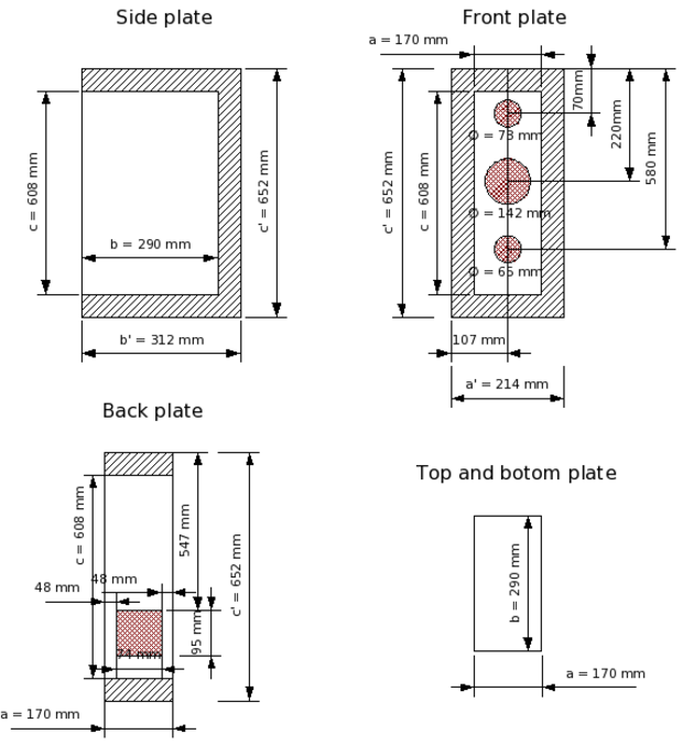
I have built the box with 22mm plates. I have designed it so that the with is as small as possible to get a good spreading of the sound. The depth is big enough to give room to the port. The height is then set to give a volume of 30l. The drawing under shows the measurements of the plates.
Crossover filter⌗
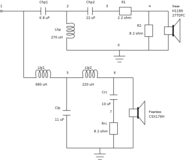
Since the tweeter has a higher sensitivity than the bass-midrange I use an L-pad attenuation circuit to reduce the sound level to match the bass-midrange. I also use a RC-shunt to modify the impedance of the bass-midrange. Everything is calculated according to the formulas given in Høytalerbok The picture below shows the resulting circuit with the values of the components. The calculations is given further down. The numbers in the circuit drawing is the node names I have used in a spice script. The spice script and the simulations is also covered further down.
L-pad attenuation circuit⌗
Since the tweeter have higher sensitivity (91dB) than the bass-midrange (86.5dB), the tweeter needs to be attenuated with \(A = 86.5 - 91 = -4.5dB\). One way of attenuation is to use an L-pad. Formula 9 and 10 gives the resistor values for the L-pad. The nearest standard values are chosen.
\[ \begin{equation} R_2 = \frac{Z_N \cdot 10^{\frac{A}{20}}}{1 - 10^{\frac{A}{20}}} = \frac{6 \cdot 10^{\frac{-4.5}{20}}}{1 - 10^{\frac{-4.5}{20}}} = 8.8\Omega \approx 8.2\Omega \end{equation} \]
\[ \begin{equation} R_1 = Z_N - \frac{R_2Z_N}{R_2 + Z_N} = 6 - + \frac{8.2 \cdot 6}{8.2 + 6} = 2.5\Omega \approx 2.2\Omega\end{equation} \]
Impedance correction⌗
The bass-midrange has a impedance which is increasing with the frequency. To compensate for that a RC-shunt can be coupled in parallel with it. Here I have used method two from the book. Formula 11 gives the frequency with \(Z=2Z_N\) which is the frequency the RC-shunt is calculated for.
\[ \begin{equation} f_{RC} = \frac{\sqrt{(2Z_N)^2 - R_e^2}}{2 \pi L_e} = \frac{\sqrt{(2 \cdot 8)^2 - 6.1^2}}{2 \pi 3 \cdot 10^{-3}} = 1811Hz\end{equation} \]
The resistor is chosen equal to the nominal impedance of the element, \(R_{RC} = Z_N = 8\Omega \approx 8.2\Omega\). Now the capacitor is calculated in formula 12.
\[ \begin{equation} C_{RC} = \frac{1}{2 \pi f_{RC} R_{RC}} = \frac{1}{2 \pi \cdot 1811 \cdot 8.2} = 10.7 \mu F \approx 10 \mu F \end{equation} \]
Crossover filter⌗
I decided to use a 3rd order filter for both elements. By studying the frequency plot of the loudspeaker elements one can see that ~2500Hz is a good dividing frequency. I therefor decided to use a dividing frequency of 2500Hz.
Low pass filter⌗
To calculate the low pass filter one first needs to now what the load impedance is. The impedance the filter sees is the bass-midrange in parallel with the RC-shunt, given in formula 13.
\[ \begin{equation} Z_{EQ} = Z_{RC} \Vert Z_E = \sqrt{R_{RC}^2 + \left(\frac{1}{2 \pi f C_{RC}}\right)^2} \Vert {\sqrt{R_e^2 + (2 \pi f L_e)^2}} \end{equation} \]
The RC-shunt makes the impedance allmost constant, and around the dividing frequency the impedance is \(Z_{EQ} \approx 6.9\Omega\). The low pass filter is then calculated in formulas 14 to 16.
\[ \begin{equation} L_{lp1} = \frac{Z_{EQ}}{2 \pi f} \cdot 1.508 = \frac{6.9}{2 \pi \cdot 2500} \cdot 1.508 = 662\mu H \approx 690\mu H \end{equation} \]
\[ \begin{equation} L_{lp2} = \frac{Z_{EQ}}{2 \pi f} \cdot 0.495 = \frac{6.9}{2 \pi \cdot 2500} \cdot 0.495 = 217\mu H \approx 220\mu H \end{equation} \]
\[ \begin{equation} C_{lp} = \frac{1}{2 \pi f Z_{EQ}} \cdot 1.333 = \frac{1}{2 \pi \cdot 2500 \cdot 6.9} \cdot 1.333 = 12.3\mu F \approx 11\mu F \end{equation} \]
High pass filter⌗
The L-pad does not modify the load impedance of the high pass filter and the impedance is the tweeter's nominal impedance \(Z_N = 6\Omega\). Formulas 17 to 19 shows the calculations of the filter.
\[ \begin{equation} C_{hp1} = \frac{1}{2 \pi f Z_N} \cdot 0.667 = \frac{1}{2 \pi \cdot 2500 \cdot 6} \cdot 0.667 = 7.1\mu F \approx 6.8\mu F \end{equation} \]
\[ \begin{equation} C_{hp2} = \frac{1}{2 \pi f Z_N} \cdot 2.006 = \frac{1}{2 \pi \cdot 2500 \cdot 6} \cdot 2.006 = 21.2\mu F \approx 22\mu F \end{equation} \]
\[ \begin{equation} L_{hp} = \frac{Z_N}{2 \pi f} \cdot 0.754 = \frac{6}{2 \pi \cdot 2500} \cdot 0.754 = 288\mu H \approx 270\mu H \end{equation} \]
Simulation⌗
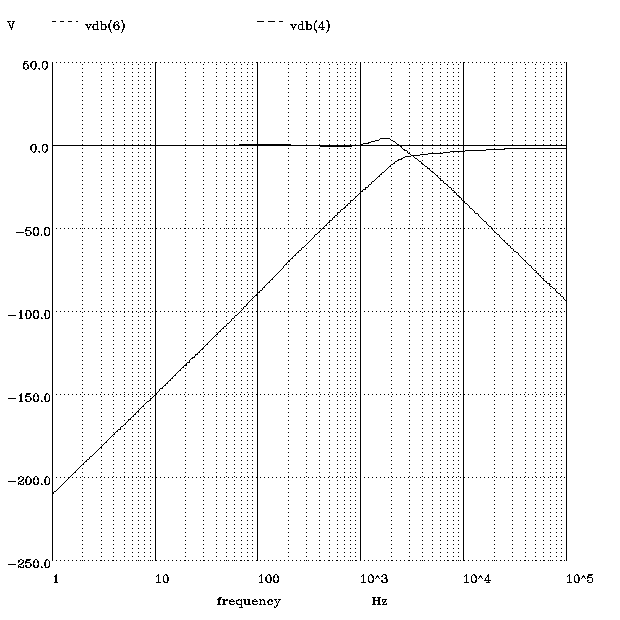
Before the crossover filter can be simulated a load for the filter needs to be decided. The easiest would be to use the the loudspeakers nominal impedance. A more advanced method which gives a more correct result is to use impedance models of the loudspeaker elements. I found a simple method for calculate a impedance model, but the link to that article is unfortunately now dead. But doing a web search for loudspeaker impedance model should return many useful links. To simulate the filter I have written a spice script. The result of the simulation is shown in the picture below.
Result⌗
